Power Supply Pump Control Module:
One of the unique aspects of radiant floor heating is the fact that each loop can be individually controlled in such a manner as to provide exactly the correct amount of energy needed for each room. And, since each room behaves differently with respect to heat gains and losses, this feature is the main reason why hydronic radiant heating systems can achieve greater comfort and efficiency, than other forms of heat distribution. For this reason, I have been a very strong proponent of multi-zone sytems.
The most practical and cost effective means of controlling multiple zones is by using individual zone motors (actuators) on each loop. These zone motors respond to a “call for heat” from the room thermostat and open the valve to allow energy to flow. Most of the zone motors utilize a 24 volt “heat motor” to operate the valve. A heating coil within the actuator is powered by 24 volt AC current. When it warms up it does two things. First, it loosens the wax in a wax bulb capsule, the, as the capsule heats up, the wax expands to push a plunger that opens the valve. (The capsule is similar to the ones inside an automobile engine thermostat) The process provides a slow opening action which reduces noise within the system. Most actuators also have, within them, a switch, which, at the end of the opening travel will close to provide a mechanism to turn on the circulator that is associated with that loop. This switch is called and “End Switch” because it closes at the end of the actuators travel. Since the switch will not operate the circulator until the valve is fully opened, the process eliminates any “dead heading” of the pump against a closed valve. This, also, reduces noise in the system and prolongs the life of the pump, which is, essentially, cooled by the water passing through it. A dead headed circulator will overheat in a very short time.
Older actuators had their current controlled by a second end switch, which, at the end of the travel would cut the current to the actuator in order to keep it from burning up either thermally or electrically. The older units would “bounce” off the end switch and that system would eventually burn up the contacts over time. Modern actuators have their current controlled internally by a solid state positive temperature controlled (PTC) resistor. The 24 Volt AC current passes through a wafer which consists of both conducting metal and non-conducting high temperature plastic. As it heats up, the plastic expands in such a manner as to, essentially, pull apart the conducting materials and reduce the current passing through it. This process is very durable and is the primary reason why modern actuators are much more reliable.
So, that’s probably more than most people want to know about zone actuators, but it is important for the system designer to know how these things work.
One problem that I’ve run into over many years in the industry is the fact that most pump control modules were never designed for radiant floor heating. The manufacturers, like so many in the industry, simply took what they had on the shelves for baseboard heating, warmed it over, and re-marketed it for radiant floor. They added some complex features that I didn’t want, made solid state circuit boards that burned out at the rumor of a spark somewhere in the system, and just weren’t up to the task. If a board burned out, it couldn’t be repaired, and the whole supply chain had to go into crisis mode to try to get a replacement out to the customer before the system froze. It really didn’t have to be this way, so I made my own.
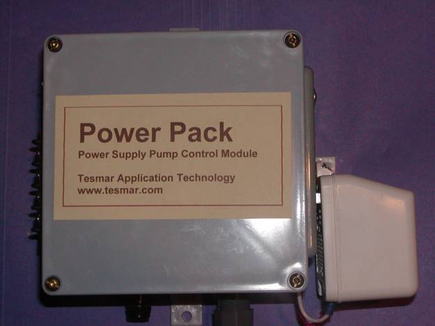
The “Power Supply Pump Control Module” , as the name implies, is a devise that provides 24 Volt AC power to the zone control system and turns on the circulator in response to a signal from the end switch(s). That’s it.
It is not uncommon for a system to have ten or more zone motors. Each one draws a certain amount of current. As explained earlier in this text, at first they draw the maximum current, and, as they warm up, the PTC resistor cuts the current down a bit. If they all come on at once they will draw significant current. That current is supplied by the power supply transformer. The transformer “transforms” the 120 Volt AC current down to a nominal 24 Volts AC. Actually, most transformers operate between a little more than 28 Volts AC down to as low as 22 Volts AC, but that’s just a technicality. If the transformer is too small, an excessive current draw will pull the transformer output down to below the minimum current level and, in time, will cause the transformer to short out internally and die. Also, if the transformer is not protected by a fuse, any time the installer makes one of those mental errors and touches the 24 volt live wires together, the transformer will fail. OOPS! Hey, after 30 years of doing this even I’ve popped a few fuses.
A lot of the “sophisticated” controllers on the market have very small (24 VA) internally “chassis” mounted transformers without fuse protection. They cannot be easily replaced. I think that’s a flaw in design.
Our controller uses an externally mounted 50 VA (Volt Amp) plug in transformer. This transformer is sufficient in size to operate at least ten actuators at maximum current draw as well as several ancillary 24 VAC components without the slightest drop in output voltage. Since it is unlikely that all of the actuators will be at maximum current draw at the same time, and, if they do, it would be a rare occurrence, I have no problem running as many as 15 actuators on this unit. If the transformer burns out, it can easily be replaced because it is plugged into a standard 24 VAC outlet on the controller. The transformer is protected internally and externally with a replaceable buss fuse. The fuse holder is externally accessible on the controller box.
120 Volt AC current is supplied to the Power Supply Pump Control Module through a grounded plug in power cord. Also, power to the circulator is routed to a 120 Volt receptacle on the side of the control module. The circulator can be fitted with a service cord and simply plugged into the controller. If, for some reason, the controller needs to be serviced, of if it fails, the circulator can then be plugged into the wall outlet, bypassing the control module and providing emergency heat until the problem can be resolved. This product requires no more involvement from the electrician on the job than to simply provide a convenient 120 VAC receptacle. Installation and replacement of the controller is “plug and Play”.
Low voltage is provided to the zone control actuators from a terminal strip which is accessible on the outside of the control module. This strip includes terminals for power from the transformer through the thermostats to the actuators and back to the transformer completing that circuit, and terminals for connecting all of the end switches to the internal relay that makes the 120 VAC contact to operate the zone circulator.
If, for some reason, the robust internal relay fails, it is also a plug in component that can easily be replaced at the jobsite.
Spare parts are available for the Power Supply Pump Control Module.
Shipping weight is 6 pounds
Includes detailed instructions
Price per Power Supply Pump Control Module is $225 plus shipping.
Although they are normally in stock Power Supply Pump Control Module is available as a special order item. Lead times vary from in stock to ten days before shipment can be made. Contact me for information on availability and shipping costs. Payment must be received before shipment.